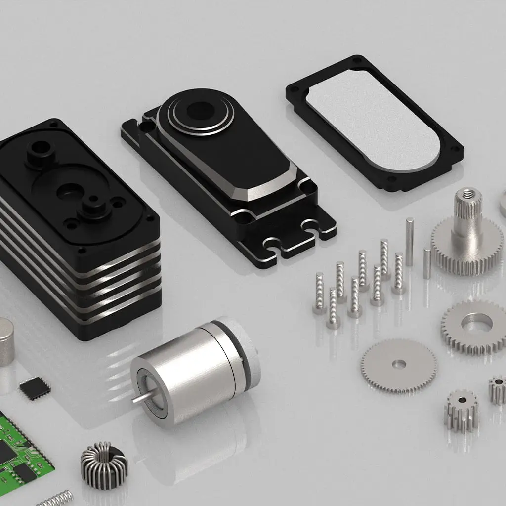
In industrial or research environments, manually testing servos is inefficient and subjective. To achieve efficient, systematic fault diagnosis, it’s recommended to build a standardized servo testing platform. This article uses GXServo as an example to explain how to design such a platform and implement structured diagnostic procedures.
1. Components of the Test Platform
A complete servo testing system should include:
- Programmable control module (e.g., STM32, Raspberry Pi);
- PWM signal or serial communication generation module;
- Servo mounting rack and load unit;
- Angle detection module (Hall encoder, optical encoder);
- Data logging module (for current, voltage, speed, temperature);
- Graphical control interface (PC or touchscreen).
GXServo’s digital models offer real-time feedback, making them ideal for integration into such systems.
2. Test Procedure Design
Standard tests should include:
- Zero-position calibration: Check whether center-position signal brings the shaft to zero;
- Response delay test: Measure time between command input and physical movement;
- Repeatability test: Send the same angle command repeatedly and log deviations;
- Load response test: Simulate real load and observe angle deviation and current draw;
- Overload protection test: Apply torque beyond rated capacity and verify protection response.
3. Automated Judgment and Alarm Mechanisms
Define thresholds such as:
- Deviations >5° = severe error;
- Response delays >200ms = abnormal;
- Failure to position after 3 retries = fault.
Use a script (e.g., in Python) to automatically issue warnings and generate logs.
4. Application Value and Conclusion
This type of platform is suitable for batch testing before GXServo shipments and for post-deployment maintenance or engineering validation. It provides unparalleled benefits in failure tracking, repeatability testing, and performance analysis.

