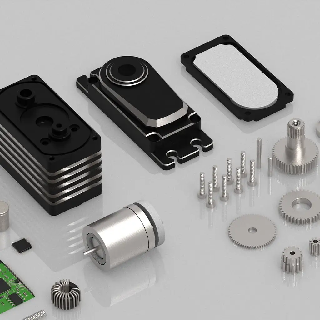
In modern automated systems, servo performance is often influenced not only by hardware but also by the control software. This is especially true for digital servos like those made by GXServo. Many apparent failures are actually caused by issues in the upper control system, microcontroller, or signal generator. This article analyzes servo malfunction testing from a software perspective, helping technical personnel locate and solve problems more efficiently.
1. Generating Correct PWM Signals
GXServo digital servos are usually controlled by PWM signals, with a standard cycle of 20ms and a high-level width that determines the angle (e.g., 1ms = 0°, 1.5ms = center, 2ms = max angle). Common signal generation methods include:
- Arduino
Servolibrary; - STM32
TIM_PWMtimer; - Raspberry Pi GPIO pulse output;
- Dedicated PWM controllers (e.g., Maestro, SignalBox).
Testing should begin with an oscilloscope or logic analyzer to verify the PWM output’s:
- Constant period, typically 50Hz;
- Duty cycle matches angle commands;
- Stability with no sudden jumps, jitter, or drift.
If anomalies are found, check whether the code logic:
- Is over-refreshing PWM in interrupts;
- Uses imprecise software timing (especially software PWM);
- Has array overflows or angle calculation errors.
2. Communication Protocol Consistency (for Digital Serial Servos)
Some advanced GXServo models support serial control (e.g., RS485 or TTL half-duplex). Failures here may stem from:
- Mismatched baud rates;
- Inconsistent parity or data bit settings;
- Missing CRC checksums;
- Incorrect command formats (e.g., writing to a read register).
Use the official serial debugging tool or a terminal app to send commands and compare responses byte-by-byte with the protocol documentation.
3. Logic Errors in Software Causing False Failures
In multitasking systems or ROS robot frameworks, software logic errors may mimic servo malfunctions:
- Motion commands not refreshed (old values repeat);
- Logic conditions not met, causing no response;
- Software cutting power too early via relays;
- Timeout controls not set, causing overrun and overheating.
Isolate high-level logic and send only basic PWM or angle commands to confirm whether the GXServo servo responds correctly.
4. Using Debugging Tools for Real-Time Analysis
Some GXServo models support real-time feedback, including position, current, load, or temperature. If the software can’t read feedback, communication may have failed, or the servo’s controller may be damaged.
Conclusion
Testing servos from the software side involves stripping down high-level abstractions and verifying base-level control to determine if issues are not hardware-related. GXServo’s digital control features provide rich interfaces and feedback that, when used effectively, can greatly enhance fault diagnosis efficiency.

